Resources > Knowledge Base > The Input File
The Input File
When you use dialogs, the program is creating and running commands for you in the background. That means you only have to type commands yourself when you choose to. That’s powerful and friendly.
Some features can be run with a single line of input, as you have already seen. Others, including some of the most powerful features, require several lines of input. This leads to the concept of an input file, which you will usually create in a macro editor. Here’s an example: Type
EE
in the CW. This opens the Excellent Editor. Copy and paste the following lines into the window that opens:
    RLE
    ID F/5 DOUBLET 5547
     FNAME 'DOUBLET.RLE '
     WAVL .6562700 .5875600 .4861300
     APS 1
     UNITS INCH
     OBB 0.000000 1.00000 6.00000 0.00000 0.00000 0.00000 6.00000
        0 AIR
        1 CV 0.0294371152971 TH 1.55999994
        1 N1 1.51431703 N2 1.51679441 N3 1.52237006
        1 GTB S 'BK7 '
        2 RAD -22.1363355597437 TH 0.28766930 AIR
        2 AIR
        3 RAD -21.9421336816345 TH 1.00000001
        3 N1 1.61502503 N2 1.62003267 N3 1.63207204
        3 GTB S 'F2 '
        4 RAD -100.2738957807268 TH 58.00665650 AIR
        4 AIR
        4 TH 58.00665650
        4 YMT 0.00000000
        5 CV 0.0000000000000 TH 0.00000000 AIR
        5 AIR
     END
Then click the Run button,  . The PAD display changes, showing an F/5 doublet. Note that the above file started with the line RLE and ended with END. Many of the features of SYNOPSYS™ can be run with a file enclosed with lines of this kind. Here, too, you usually have a choice of whether to type the data yourself or let the program create it for you. The latter is a big time saver. If you go to the MPE dialog (Menu, Perspective drawings), make your selection between wire-frame, rotating wire-frame, solid drawing, rotating solid drawing, and so on, the program creates and runs the appropriate input file. To illustrate, get out the lens in library location 1 again, and type
MPE
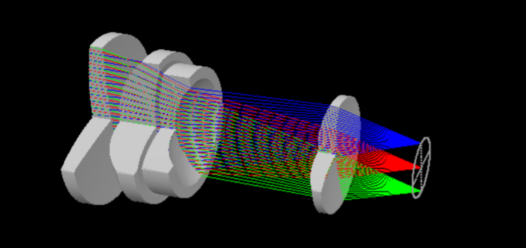
and select the Rotating Solid Model, Cutaway view, TFAN at fields 0.0, 1.0, -1.0. Then click Execute. Drag with the mouse on the picture, and it will rotate about.

Now type LMM in the CW, or use the menu items MACro | Load the last menu sequence. A new editor window opens, containing the input file for the above picture:
    RSOLID 0 0 0 0 0
    CUTAWAY
    PLOT
    RED
    PUP 2 1 21
    TRACE P 0 0 21
    BLUE
    TRACE P 1 0 21
    GREEN
    TRACE P -1 0 21
    END
You can save, edit, and run this file yourself, to make a similar picture for a different lens, for example, without wading through the dialog all over again. That’s a time-saver for sure.
Let us finish this orientation chapter by mentioning that, for optimization, you will define your variables with a file
    PANT
    …
    END
and the merit function with a file
    AANT
    …
    END
The following chapters will show many examples of how you use these formats.
Oh … we almost forgot: Try the Video Tutorial, which you can download from our website. That tutorial covers many topics in greater detail. And be aware that when you install the program you have a very friendly Tutorial Manual available. Just type
HELP TM.
P.S. And don’t neglect to read about the Artificial Intelligence feature in the User’s Manual. No other optics code has anything like it.
